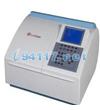
S5 Series Battery Monitoring and Validation System has been designed specifically for your UPS battery cabinet.
Our patented and proven impedance measurement technology finds bad batteries well before they pose a risk to your critical systems.
Plus, with battery sensing harnesses pre-designed and tested for your battery system, installation time is cut in half while increasing system reliability.
Key System Features
BTECH Monitors Key Battery Parameters in Real Time: System Voltage, Float, Charge and Discharge Current, plus ambient and pilot cell temperatures
Programmed Cell Impedance Measurement: Up to 24x / Day
Programmable Test & Out-of-Limits Alarms
Battery Discharge Data Logging
Up to 480 Individual Cells and 4 Strings per system
Individual String Current Monitoring for multi-string systems
Complete Isolation from the Battery String
No PC Required
Facility Management System Integration
MODBUS over TCP/IP for simple third-party software integration
(6) User-configurable Dry Contact Alarms
Alarm and Data Acquisition Options
Local: RS-232 and USB
Remote: 56k Modem and Integral Ethernet
Alarms: Text Message to multiple cell phones, pagers or e-mail addresses, through BVM Software or FMS integration
Safety
BTECH Quick-Disconnect Safety Fuses simplify battery replacements while protecting personnel during installation and maintenance
System Specifications
Measurement Capability: - Total Voltage: 0-600V - Total Number Strings: 4 - Unit Voltage: 1-16 VDC Unit Impedance 100µW to 20mW Temperature - Unit and Ambient: -32°F to 160°F Discharge Events: - Date & Time - System Voltage - Load Current - Power Removed Discharge Logging: Programmable Connection Capacity: - Total Connection Points: 480 - Total Number of Parallel Strings: 4 Measurement Accuracy & Repeatability: - System Voltage: +/ -0.1% Full Scale - Unit Voltage: +/ -0.1% of Reading - Unit Impedance: +/ -0.01 mW - Temperature: +/ -1.0°F |
Power Requirements: -110-250 VAC (UPS Protected Power) Enclosure: - Controller: Metal, Rack or Wall Mount - 24 Unit DCM: Flame Retardant Poly LED Indicators - VM24 DCM: - Green = Power On LED Indicators - SCM600 Controller: - Green = Summary No Alarms - Yellow = Summary Maintenance Alarms - Red = Summary Critical Alarms - Red Equipment = Module not Communicating - Alternating Green = Performing Measurement Software: - BVM 4.1 Windows® based software package designed for Windows® XP and higher CE Mark |